$24.36
$29.48
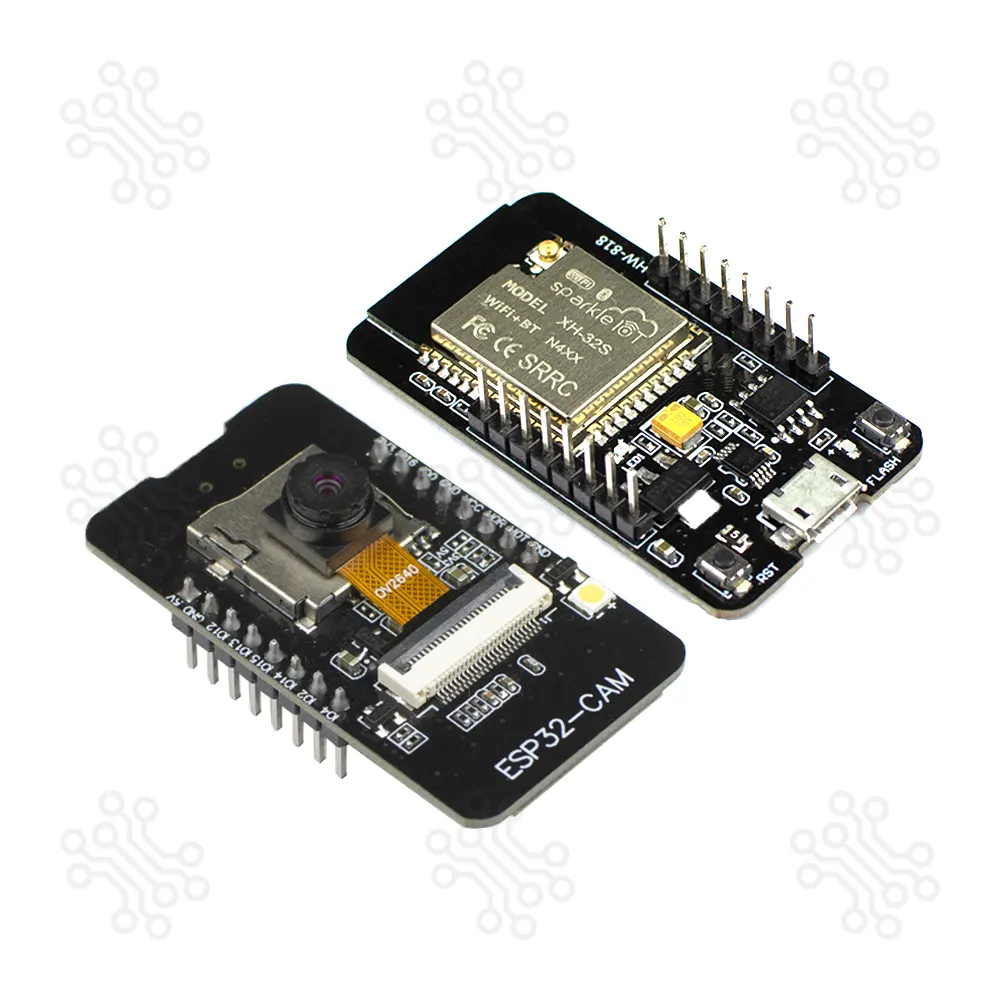
Description of ESP32 Camera Module The ESP32-CAM is a very small camera module with the ESP32-S chip, designed as a low-cost board that combines a 2MP OV2640 camera and an onboard Micro USB serial port to interface. Along with the OV2640 camera and several GPIOs for connecting peripherals, it also includes a microSD card slot that can be used to store captured images or files to serve to clients. Powered by the ESP32-S dual-core processor running at up to 240 MHz, it includes 520 KB of SRAM, 4 MB of PSRAM, and 4 MB of flash memory, providing strong performance for image capture, video streaming, and edge AI processing. This makes it a powerful yet affordable choice for developers and hobbyists. This board supports microSD storage, offers both PCB and external antenna options, and includes two programmable LEDs—a white flash LED and a blue status LED. Combined with dedicated Reset and Flash buttons for easy programming and control, its efficient layout and reliable wireless connectivity make the ESP32-CAM an excellent choice for compact, intelligent camera-based IoT and AI-driven applications. Technical Specification Parameter Details CPU Xtensa Dual-Core 32-bit LX6 (240 MHz, up to 600 DMIPS) SRAM 520 KB External PSRAM 4 MB Flash Memory 4 MB Internal Flash Wi-Fi 802.11 b/g/n Bluetooth Bluetooth v4.2 BR/EDR & BLE Camera Sensor 2 MP OV2640 Resolution UXGA (1600 × 1200) Output Formats YUV422, YUV420, RGB565, RGB555, 8-bit compressed Frame Rate 15 – 60 fps (Depends on Resolution) Flash LED Built-in Flash LED microSD Support Up to 32GB (FAT32) Security WPA/WPA2, WAPI, Secure Boot, Flash Encryption Crypto Hardware AES, SHA-2, RSA, ECC, RNG Deep Sleep Current ≈ 5 µA Dimension 48 x 27 x 10 mm ESP32-CAM Pinout Reference The ESP32-CAM has 16 pins in total. For convenience, pins with similar functionality are grouped together. The pinout is as follows: The ESP32-S chip has 32 GPIO pins in total, but because many of them are used internally for the camera and the PSRAM, the ESP32-CAM only has 10 GPIO pins available. These pins can be assigned a variety of peripheral duties, such as UART, SPI, ADC, and Touch, by programming the appropriate registers. Which ESP32-CAM GPIOs are safe to use? Although the ESP32-CAM has 10 GPIO pins with various functions, some of them may not be suitable for your projects. The table below shows which pins are safe to use and which pins should be used with caution. ✅ – Your top priority pins. They are perfectly safe to use. ⚠️ – Pay close attention because their behavior, particularly during boot, can be unpredictable. Also, some GPIOs are shared with the microSD card. So use them with caution. ❌ – It is recommended that you avoid using these pins. Label GPIO Safe to use? Reason D0 0 ⚠️ must be HIGH during boot and LOW for flashing TX0 1 ❌ Tx pin, used for flashing and debugging D2 2 ⚠️ must be LOW during boot; unusable with microSD RX0 3 ❌ Rx pin, used for flashing and debugging D4 4 ⚠️ On-board LED; unusable with microSD D12 12 ⚠️ must be LOW during boot; unusable with microSD D13 13 ⚠️ cannot be used when microSD card is present D14 14 ⚠️ cannot be used when microSD card is present D15 15 ⚠️ must be HIGH during boot, prevents startup log if pulled LOW, cannot be used when microSD card is present RX2 16 ✅ Power Supply The ESP32-CAM offers three reliable power input options, with the on-board Micro-USB connector being one of its most convenient and advanced features. Because the board already includes a built-in Micro-USB port, you do not need any additional USB-to-UART or power module for supplying 5V power—making the setup simpler and more efficient. The module also provides 3.3V output from the onboard voltage regulator (AMS1117). Although the board can technically operate from either pin, powering it through the 3.3V pin often causes instability, unexpected resets, or Wi-Fi issues during high-load operations. For reliable and consistent performance, it is strongly recommended to power the ESP32-CAM through the 5V pin. Additionally, the VCC pin normally outputs 3.3V from the onboard voltage regulator. By adjusting the nearby zero-ohm link (solder bridge), the VCC output can be changed to 5V, offering flexibility for different hardware requirements and project designs. How to Program? The ESP32 Camera Module is an upgraded version of the ESP32 S-CAM with an onboard programmer. Just connect it to a computer and start programming the ESP32 without the need for any external adapter or programmer. The ESP32 Camera Module can be programmed using Arduino IDE, PlatformIO, or Espressif IDE. These platforms provide easy access to libraries for Wi-Fi, Bluetooth, camera control, and AI/vision functions, making development quick and flexible. A quick search on Google will yield numerous online tutorials covering these platforms. Some notable examples include: Installing the ESP32 Board in the Arduino IDE Applications The ESP32-CAM suit for IoT applications such as: Image capture and upload for smart home systems Wireless monitoring Intelligent agriculture QR wireless identification facial recognition Documents Camera (OV2640) Datasheet ESP32 Camera Module Schematic Packaging Details 1 × ESP32 Camera Module Warranty and Replacement TechShopBD offers up to one year of warranty and replacement support for its products, depending on the supplier(s) and product(s). The specific warranty duration for each product can be found on the respective product page. To be eligible for warranty and replacement support, customers must agree to our terms and conditions. Attention Note: This item is non-returnable. If this item arrives damaged or is not functioning properly, please don’t hesitate to contact us to determine if further action is required. Need Help? Our engineers are available to assist you. If you have any queries, please leave a comment below or call 09678110110 from 09:00 am to 06:00 pm (7 days a week). You can also reach us via WhatsApp or Facebook Inbox
Esp