$18.76
$28.14
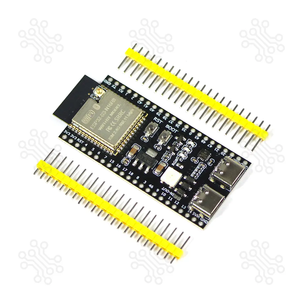
Description of ESP32 S3 DevKitC1 N16R8 Development Board Dual USB Type C The ESP32 S3 DevKitC-1 N16R8 is an entry-level development board equipped with ESP32-S3-WROOM-1 a general-purpose Wi-Fi Bluetooth Low Energy MCU module that integrates complete Wi-Fi and Bluetooth Low Energy functions. It perfect for AI, IoT, and advanced embedded applications. With dual-core Xtensa LX7 processors, it brings enhanced computing power for machine learning, neural networks, and signal processing projects. The board’s versatility is enhanced with its Dual USB-C ports, making it easier than ever to power, program, and interface with external devices. This board features a 16MB embedded flash, 512KB internal SRAM, and 8MB PSRAM, making it suitable for memory-intensive applications. It supports WiFi 802.11 b/g/n and Bluetooth 5 (BLE). The board offers up to 34 GPIO pins and operates at 3.3V logic level. It can be powered via USB Type-C or an external 5V supply. With built-in native USB support, it enables easy programming and debugging without requiring an external USB-to-UART converter. Most of the module’s I/O pins are easily accessible through the pin headers located on both sides of the board. Developers can connect various peripherals using jumper wires or place the board directly on a breadboard. Before use, the header pins must be soldered onto the board. Technical Specification Parameter Function Details ESP32-S3-WROOM-1 Wireless Module Wi-Fi BLE MCU modules with rich peripherals; acceleration for neural network and signal processing; WROOM-1 with PCB antenna. 5 V to 3.3 V LDO Power Regulation Converts 5 V input to stable 3.3 V output Pin Headers GPIO Access All usable GPIO pins exposed (except flash SPI) for easy interfacing and programming USB-to-UART Port Power & UART Communication Used for power supply, firmware flashing, and UART communication via onboard bridge Boot Button Firmware Download Used with Reset to enter Firmware Download mode via serial port Reset Button System Reset Restarts the board USB Port Native USB Interface Full-speed USB OTG (USB 1.1) for power, flashing, communication, and JTAG debugging USB-to-UART Bridge USB–UART Interface Supports communication up to 3 Mbps RGB LED Status Indicator Addressable LED controlled by GPIO38 3.3 V Power On LED Power Indicator Turns on when USB power is supplied Note: For boards with Octal SPI flash/PSRAM memory embedded ESP32-S3-WROOM-1 modules, the pins GPIO35, GPIO36 and GPIO37 are used for the internal communication between ESP32-S3 and SPI flash/PSRAM memory, thus not available for external use. Block Diagram The block diagram below shows the components of ESP32-S3-DevKitC-1 and their interconnections. Power Supply Options There are three mutually exclusive ways to provide power to the board: USB-to-UART Port and ESP32-S3 USB Port (either one or both), default power supply (recommended) 5V and G (GND) pins 3V3 and G (GND) pins ESP32-S3-DevKitC-1 Pinouts Header Block The two tables below provide the Name and Function of the pins on both sides of the board (J1 and J3). The pin names are shown in ESP32-S3-DevKitC-1 - front. The numbering is the same as in the Board Schematic (PDF). J1 No. Name Type Function 1 3V3 P 3.3 V power supply 2 3V3 P 3.3 V power supply 3 RST I EN 4 4 I/O/T RTC_GPIO4, GPIO4, TOUCH4, ADC1_CH3 5 5 I/O/T RTC_GPIO5, GPIO5, TOUCH5, ADC1_CH4 6 6 I/O/T RTC_GPIO6, GPIO6, TOUCH6, ADC1_CH5 7 7 I/O/T RTC_GPIO7, GPIO7, TOUCH7, ADC1_CH6 8 15 I/O/T RTC_GPIO15, GPIO15, U0RTS, ADC2_CH4, XTAL_32K_P 9 16 I/O/T RTC_GPIO16, GPIO16, U0CTS, ADC2_CH5, XTAL_32K_N 10 17 I/O/T RTC_GPIO17, GPIO17, U1TXD, ADC2_CH6 11 18 I/O/T RTC_GPIO18, GPIO18, U1RXD, ADC2_CH7, CLK_OUT3 12 8 I/O/T RTC_GPIO8, GPIO8, TOUCH8, ADC1_CH7, SUBSPICS1 13 3 I/O/T RTC_GPIO3, GPIO3, TOUCH3, ADC1_CH2 14 46 I/O/T GPIO46 15 9 I/O/T RTC_GPIO9, GPIO9, TOUCH9, ADC1_CH8, FSPIHD, SUBSPIHD 16 10 I/O/T RTC_GPIO10, GPIO10, TOUCH10, ADC1_CH9, FSPICS0, FSPIIO4, SUBSPICS0 17 11 I/O/T RTC_GPIO11, GPIO11, TOUCH11, ADC2_CH0, FSPIID, FSPIIO5, SUBSPID 18 12 I/O/T RTC_GPIO12, GPIO12, TOUCH12, ADC2_CH1, FSPIIO6, SUBSPICLK 19 13 I/O/T RTC_GPIO13, GPIO13, TOUCH13, ADC2_CH2, FSPIIO7, SUBSPIQ 20 14 I/O/T RTC_GPIO14, GPIO14, TOUCH14, ADC2_CH3, FSPIWP, FSPIIO8, SUBSPIWP 21 5V P 5 V power supply 22 G G Ground J3 No. Name Type Function 1 G G Ground 2 TX I/O/T U0TXD, GPIO43, CLK_OUT1 3 RX I/O/T U0RXD, GPIO44, CLK_OUT2 4 1 I/O/T RTC_GPIO1, GPIO1, TOUCH1, ADC1_CH0 5 2 I/O/T RTC_GPIO2, GPIO2, TOUCH2, ADC1_CH1 6 42 I/O/T MTMS, GPIO42 7 41 I/O/T MTDI, GPIO41, CLK_OUT1 8 40 I/O/T MTDO, GPIO40, CLK_OUT2 9 39 I/O/T MTCK, GPIO39, CLK_OUT3, SUBSPICS1 10 38 I/O/T GPIO38, FSPIWP, SUBSPIWP, RGB LED 11 37 I/O/T SPIDQS, GPIO37, FSPIQ, SUBSPIQ 12 36 I/O/T SPIIO7, GPIO36, FSPICLK, SUBSPICLK 13 35 I/O/T SPIIO6, GPIO35, FSPID, SUBSPID 14 0 I/O/T RTC_GPIO0, GPIO0 15 45 I/O/T GPIO45 16 48 I/O/T GPIO48, SPICLK_N, SUBSPICLK_N_DIFF 17 47 I/O/T GPIO47, SPICLK_P, SUBSPICLK_P_DIFF 18 21 I/O/T RTC_GPIO21, GPIO21 19 20 I/O/T RTC_GPIO20, GPIO20, U1CTS, ADC2_CH9, CLK_OUT1, USB_D 20 19 I/O/T RTC_GPIO19, GPIO19, U1RTS, ADC2_CH8, CLK_OUT2, USB_D- 21 G G Ground 22 G G Ground Note: P: Power supply; I: Input; O: Output; T: High impedance. How to Program ESP32-S3-DevKitC-1?? The ESP32-S3-DevKitC-1 is a development board based on ESP32-S3-WROOM-1 modules, which include a microcontroller with Wi-Fi and Bluetooth LE. It exposes most of its I/O pins through headers, allowing you to connect sensors, actuators, and other devices. You can program this board using different IDE platforms, depending on your preference and project type. The most common options are: Arduino IDE – simple and beginner-friendly, ideal for quick testing or IoT projects. ESP-IDF – the official framework from Espressif, more powerful for advanced features and performance tuning. Before programming, make sure: You have a USB cable to connect the board. Your computer recognizes the board’s USB-to-serial interface. To test the board, you can upload a simple LED blink program using Arduino IDE. Install ESP32 support in Arduino IDE Follow the guide: “Installing ESP32 Board in Arduino IDE”. Select the board Go to Tools → Board and choose ESP32S3 Dev Module. Write the code Example for blinking the RGB LED (usually on GPIO48) Application The ESP32 S3 DevKitC1 N16R8 Development Board Dual USB Type C is ideal for: IoT Projects Home Automation AIoT Applications Robotics Control USB-Based Development Wireless Communication Packaging Detail 1 × ESP32 S3 DevKitC1 N16R8 Development Board Dual USB Type C 2 × Male Header Connector (22 Pin) ESP32 S3-Based Projects ESP32 S3 Web Voice Broadcasting Document ESP32-S3-Datasheet ESP32-S3-WROOM-1 Datasheet ESP32-S3-DevKitC1 N16R8 Schematic Warranty and Replacement TechShopBD offers up to one year of warranty and replacement support for its products, depending on the supplier(s) and product(s). The specific warranty duration for each product can be found on the respective product page. To be eligible for warranty and replacement support, customers must agree to our terms and conditions. Attention Note: This item is non-returnable. If this item arrives damaged or is not functioning properly, please don’t hesitate to contact us to determine if further action is required. Need Help? Our engineers are available to assist you. If you have any queries, please leave a comment below or call 09678110110 from 09:00 am to 06:00 pm (7 days a week). You can also reach us via WhatsApp or Facebook Inbox
Esp