$13.3
$19.29
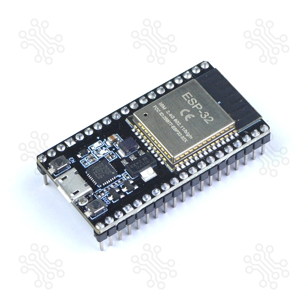
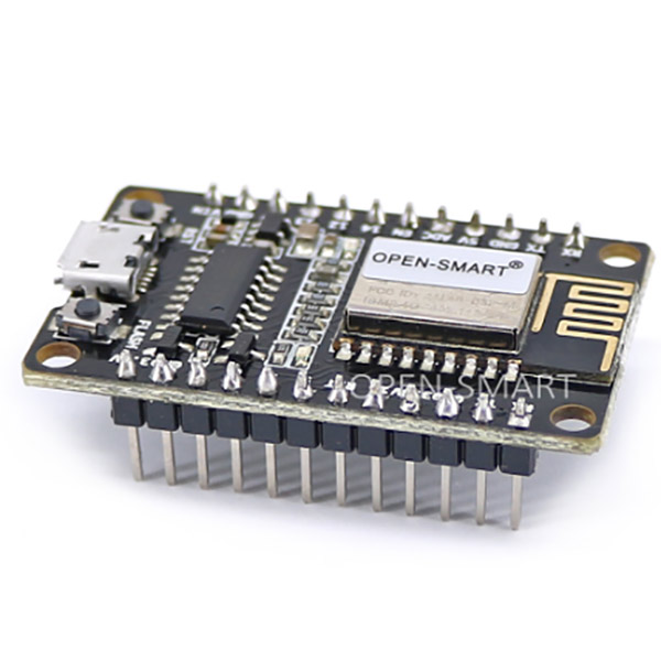
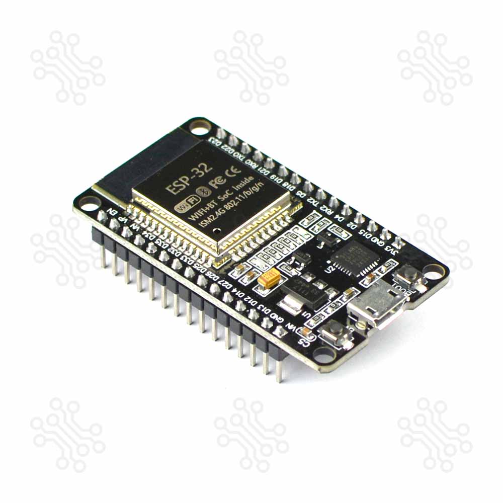
Description of ESP32 Development Board CP2102 Chip 38 Pin The ESP32 Development Board (38-Pin) is a versatile development board built around the ESP-WROOM-32 module from Espressif System. It is designed to support modern embedded and wireless projects by combining a powerful processing unit with integrated connectivity features. With its well-organized pin layout and onboard components, the board is suitable for both rapid prototyping and structured development work. This board includes a dual-core 32-bit processor, along with integrated Wi-Fi and Bluetooth, allowing seamless communication in connected applications. The onboard CP2102 USB-to-UART converter ensures stable and straightforward programming through a standard USB connection. Due to its balanced performance, low power requirements, and broad software compatibility, the ESP32 Development Board is widely used in IoT systems, automation solutions, robotics projects, and general embedded development. When comparing the ESP32 to the Arduino, Atmel, or PIC, you'll find that the ESP32 Devkit V1 offers more pins, a faster processor, and superior overall performance. If you’re just getting started, check out our ESP32 Tutorials in Bangla. Specification Parameter Function Microcontroller ESP-WROOM-32 Processor Xtensa dual-core 32-bit LX6 Clock Speed 240 MHz RAM 520 KB SRAM, 448 KB ROM, 16 KB SRAM in RTC Flash Memory 4 MB WiFi 802.11b/g/n Bluetooth V4.2 GPIOs 25 Antenna On-board PCB antenna Programming Port Micro USB USB to UART CP2102 Dimensions 49 × 26 mm (±2) Compared to others ESP32 Development Board CP2102 Chip 38 Pin is a powerful dual-core board with Wi-Fi and Bluetooth, offering many GPIO pins for complex IoT projects. ESP8266 NodeMCU V2 is a simple single-core Wi-Fi board with fewer pins, suitable for basic IoT tasks. Arduino UNO is a beginner-friendly board with no built-in wireless, slower speed, and limited pins, ideal for basic electronics and prototyping. Feature ESP32 38 Pin ESP8266 Arduino UNO Clock Speed 240 MHz 160 MHz 16 MHz WiFi Yes Yes No Bluetooth Yes No No Memory 520 KB SRAM, 4 MB Flash 160 KB SRAM, 4 MB Flash 2 KB SRAM, 32 KB Flash GPIOs 25 17 20 ESP32 Pin Diagram J1 No. Name Type Function 1 3V3 P 3.3 V power supply 2 EN I CHIP_PU, Reset 3 VP I GPIO36, ADC1_CH0, S_VP 4 VN I GPIO39, ADC1_CH3, S_VN 5 IO34 I GPIO34, ADC1_CH6, VDET_1 6 IO35 I GPIO35, ADC1_CH7, VDET_2 7 IO32 I/O GPIO32, ADC1_CH4, TOUCH_CH9, XTAL_32K_P 8 IO33 I/O GPIO33, ADC1_CH5, TOUCH_CH8, XTAL_32K_N 9 IO25 I/O GPIO25, ADC2_CH8, DAC_1 10 IO26 I/O GPIO26, ADC2_CH9, DAC_2 11 IO27 I/O GPIO27, ADC2_CH7, TOUCH_CH7 12 IO14 I/O GPIO14, ADC2_CH6, TOUCH_CH6, MTMS 13 IO12 I/O GPIO12, ADC2_CH5, TOUCH_CH5, MTDI 14 GND G Ground 15 IO13 I/O GPIO13, ADC2_CH4, TOUCH_CH4, MTCK 16 D2 I/O GPIO9, D2 2 17 D3 I/O GPIO10, D3 2 18 CMD I/O GPIO11, CMD 2 19 5V P 5 V power supply J3 No. Name Type Function 1 GND G Ground 2 IO23 I/O GPIO23 3 IO22 I/O GPIO22 4 TX I/O GPIO1, U0TXD 5 RX I/O GPIO3, U0RXD 6 IO21 I/O GPIO21 7 GND G Ground 8 IO19 I/O GPIO19 9 IO18 I/O GPIO18 10 IO5 I/O GPIO5 11 IO17 I/O GPIO17 3 12 IO16 I/O GPIO16 3 13 IO4 I/O GPIO4, ADC2_CH0, TOUCH_CH0 14 IO0 I/O GPIO0, ADC2_CH1, TOUCH_CH1, Boot 15 IO2 I/O GPIO2, ADC2_CH2, TOUCH_CH2 16 IO15 I/O GPIO15, ADC2_CH3, TOUCH_CH3, MTDO 17 D1 I/O GPIO8, D1 2 18 D0 I/O GPIO7, D0 2 19 CLK I/O GPIO6, CLK 2 Note: (1,2) P: Power supply; I: Input; O: Output. (1,2,3,4,5,6) The pins D0, D1, D2, D3, CMD and CLK are used internally for communication between ESP32 and SPI flash memory. They are grouped on both sides near the USB connector. Avoid using these pins, as it may disrupt access to the SPI flash memory/SPI RAM. (1,2) The pins GPIO16 and GPIO17 are available for use only on the boards with the modules ESP32-WROOM and ESP32-SOLO-1. The boards with ESP32-WROVER modules have the pins reserved for internal use. Power Supply There are three mutually exclusive ways to provide power to the board: Micro USB port, default power supply 5V and GND header pins 3V3 and GND header pins Warning The power supply must be provided using one and only one of the options above, otherwise the board and/or the power supply source can be damaged. How to Program? The ESP32 can be programmed using various platforms, such as the Espressif IDE, Thonny IDE, PlatformIO with Visual Studio Code, and the Arduino IDE. A quick search on Google will yield numerous online tutorials covering these platforms. Some notable examples include: Installing the ESP32 Board in the Arduino IDE ESP32 Programming using Espressif IDE ESP32 Arduino Examples Once you have installed ESP Boards via the Board Manager of Arduino IDE, you can find various example projects, including Blink, Digital Read Serial, Analog Read Serial, Button, PWM, WiFI Web Server, WiFi Web Client, etc. From the Arduino IDE, go to Tools > Board and select esp32 > ESP32 Dev Module. Once you have the ESP32 board chosen, go to File > Examples. Inside that folder, you will find various example sketches for different functionalities like WiFi, Bluetooth, Sensors, and more. Packaging Details 1 × ESP32 Development Board CP2102 Chip 38 Pin Documents ESP32 Datasheet ESP32 Development Board with CP2102 38 Pin Schematic Warranty and Replacement TechShopBD offers up to one year of warranty and replacement support for its products, depending on the supplier(s) and product(s). The specific warranty duration for each product can be found on the respective product page. To be eligible for warranty and replacement support, customers must agree to our terms and conditions. Attention Note: This item is non-returnable. If this item arrives damaged or is not functioning properly, please don’t hesitate to contact us to determine if further action is required. Need Help? Our engineers are available to assist you. If you have any queries, please leave a comment below or call 09678110110 from 09:00 am to 06:00 pm (7 days a week). You can also reach us via WhatsApp or Facebook Inbox
Esp